 Menu
Menu
- Home
- Managing An Irrigation System
- Planning System Hardware
- Farm Irrigation Systems & Cost Analysis
- Water Resource Development
- Micro Irrigation Handbook
- Related Links

Hydraulic Ram Pumps
Larry M. Curtis,Biosystems Engineer- Soil & Water
Ted W.Tyson, Biosystems Engineer-Irrigation
The hydraulic ram pump is a motorless low-flow-rate pump which uses flowing water as its energy source. The hydraulic ram can be used where small quantities of water are required, such as for domestic water supplies or livestock watering. It is also practical where conventional power for pumping water is not available, such as remote areas where the installation of electric service would be uneconomical or where an internal combustion engine would be impractical.
When hydraulic ram pumps are properly sized and installed, flow rates of 14 gallons per minute or 20,000 gallons per day are possible. Water can be lifted to elevations of up to 400 feet, depending upon the quantity and velocity of water flow at the source.
The components of a hydraulic ram pumping system are shown in Figures 1 and 2. They are: (1) a water supply from a lake, spring, creek, canal, or artesian well; (2) a drive pipe (diverting water from the source to the pump); (3) a hydraulic ram pump; and (4) a delivery pipe to the discharge point.
Principles Of Operation
In a hydraulic ram pump, water flows down the drive pipe to the ram. It is diverted around the pump through an exterior valve until the maximum velocity is obtained for existing flow conditions. When a suitable high velocity is obtained, the valve suddenly closes. Water is diverted through an interior valve and into the air chamber. The momentum of the flowing fluid forces water into the air chamber under pressure. Water moves into the air tank until the pressure inside the air chamber equalizes and overcomes the driving force behind it. At the proper operating velocity, equilibrium is not approached gradually; rather, the water surges into the tank, compressing the air in the tank, and then the air attempts to rebound. As the rebound, or expansion of compressed air begins, the interior valve closes, trapping the water under pressure in the air tank. That pressure is released as the water flows through the delivery pipe to its destination.
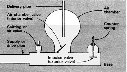
Figure 1. Components Of A Hydraulic Ram
Due to the design of the valve system, a small amount of air is trapped and forced into the air chamber with each stroke. This prevents the air chamber from becoming water logged. It also allows the proper amount of air to be maintained in the air tank so that its expansion and contraction allows the water to flow smoothly through the delivery pipe rather than surging strongly with each stroke.
Depending upon the quantity and velocity of the flow, between 25 and 100 strokes will occur per minute as the pump operates.
Pump Selection
The ram pump you select should produce the flow rate needed for your particular situation. The pump flow rate and pressure depend on the quantity and speed of flow of the water source. The quantity should be determined by measuring the water source flow. The speed of flow will depend on the change of elevation or fall between the inlet to the drive pipe and between the inlet to the pump.
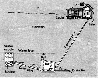
Figure 2. Hydraulic Ram Installation For A Farmstead.
The relationship between pump output and water source can be expressed as follows:
Q = (V) (F) (0.60)
(E)
where
Q = pumping flow rate; gallons per minute (GPM);
F = vertical fall from the drive pipe (ft.);
V = available flow through the drive pipe (GPM);
E = vertical distance that the water is to be raised (ft.);
and
0.60 = efficiency of a ram installation (this will vary).
Assume that a ram pump is to be installed on a creek which flows at a rate of 10 GPM. The pump is located so that the vertical fall along the drive pipe is 8 feet. The vertical elevation from the pump to the tank at which the water is to be delivered is 60 feet. Under those conditions:
Q = (10 GPM) (8 ft.) (0.60)
(60 ft.)
Q = 0.8 GPM or 1152 gal./day
Thus, a maximum of 0.80 GPM will be pumped if a hydraulic ram pump is used under these conditions.Table 1 lists characteristics of hydraulic ram pumps which will help when making your selection.
Ram Pump Installation
The requirements for installing hydraulic ram pumps are most often dictated by the location of the water source and the desired delivery point. For proper operation, the length of the drive pipe should be three to five times the vertical fall. The length of the delivery pipe is not considered in the equation shown earlier because friction losses are normally small due to low flow rates.
For extremely long discharge pipe lengths or high flow rates, however, friction losses in the delivery pipe will affect pump flow rates. In no case should the diameter of the delivery pipe be reduced below that recommended by the manufacturer.
Ram pumps can be installed in groups when a single pump does not meet the stream capacity or when the flow rate of the water source varies during the year.
Sizing A Ram Pump
To ensure that the ram pump you select is correctly sized, complete the data sheet at the bottom of the page and send it to the manufacturer.
Table 1. Sizes Of Rams, Pipe Size, And Capacities Required.*
Size, diameter of drive pipe in inches |
Diameter of delivery pipe in inches |
Minimum GPM required for operation |
Capacity per day in gallons |
1 1 1/2 2 2 1/2 3 |
1/2 3/4 1 1 1/4 1 1/2 |
6 14 25 35 60 |
100-2,100 150-3,600 350-7,000 500-10,000 700-20,000 |
*Some companies make rams up to 8 inches in size.
References
1. Graham, Frank D. 1943. Audels Pumps, Hydraulics and Air Compressors. Theo. Audel & Co., 49 West 23rd St., N.Y., N.Y., pp. 761-784.
2. Harrison, Dalton S., P.E., 1980. Hydraulic Ram Pumps, Fact Sheet No. AE 19, Extension Division, Agricultural Engineering, University of Florida, Gainesville, FL, February, 1980.
3. Matson, Howard. 1931. The Hydraulic Ram. Cir. No. 246, Extension Division, College of Agriculture, University of Kentucky, Lexington, KY, June 1931.
4. Privette, Charles V. 1979. Hydraulic Ram. Irrigation Fact Sheet No. 4, Agricultural Engineering Department, Clemson University, Clemson, SC.
Hydraulic Ram Pump Site Characteristics
1. Available supply of water in gallons per minute. ________GPM
2. Vertical fall in feet (measure the amount of vertical fall in feet from the water level of the drive pipe inlet down to the level of the foundation on which the ram will rest). ________feet
3. Distance from source of supply to ram. ________feet
4. Vertical lift in feet (measure the vertical lift in feet from the level of the foundation on which the ram will rest up to the elevation of the highest point to which the water will be delivered). ________feet
5. Distance in feet from ram to delivery tank. ________feet
6. Number of gallons required to be delivered per day _____gallons
NAME_______________________________ADDRESS____________________________________
Publication No.
ANR-481 |
JAN. 1999 |
Larry M. Curtis, Biosystems Engineer, Professor, Biosystems Engineering, and Ted W. Tyson, Biosystems Engineer, Associate Professor, Biosystems Engineering |
Issued in furtherance of Cooperative Extension work in agriculture and home economics, Acts of May 8 and June 30, 1914, and other related acts, in cooperation with the U.S. Department of Agriculture. The Alabama Cooperative Extension System (Alabama A&M University and Auburn University) offers educational programs, materials, and equal opportunity employment to all people without regard to race, color, national origin, religion, sex, age, veteran status, or disability.
This document is author-produced (unedited).

