 Menu
Menu
- Home
- Managing An Irrigation System
- Planning System Hardware
- Farm Irrigation Systems & Cost Analysis
- Water Resource Development
- Micro Irrigation Handbook
- Related Links

The Center Pivot Irrigation System
Operational, Energy, and Planning Requirements
Larry M. Curtis, Agricultural Engineer-Soil & Water
Ted W. Tyson, Agricultural Engineer-Irrigation
To understand the energy requirements of a center pivot irrigation system, it is helpful to know how the pressure changes in the system from one location to another. However, it is also important to understand how such a system functions.
A typical center pivot system is shown in Figure 1. The system consists of a lateral pipeline with sprinklers attached. The lateral line is composed of sections called towers. Each tower is supported by a truss structure, a support frame, and a wheel-drive mechanism. The lateral line irrigates a circular area by rotating around a central, fixed pivot point. Water is supplied to the pivot point from a well at the pivot or through an underground pipeline from a remote water source such as a lake or stream.
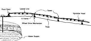
Figure 1. Center Pivot Irrigation System.
Operating A Center Pivot System
This system is propelled by electric motors or hydraulic motors located on each wheel-drive mechanism. Power for the pivot is supplied by an engine-drive generator, a hydraulic pump located at the center point, or by an underground cable which conveys electric power from a commercial source to the center pivot.
Some pivot systems can be towed to adjacent circular areas by disconnecting the pivot point, turning the wheels 90 degrees, and attaching a towing vehicle at the pivot point.
Center pivot systems vary in size from single tower systems that irrigate 10 acres or less to systems with 15 or more towers that irrigate several hundred acrie's. lypical systems range from 40 to 200 acres.
The flow rate required by the pivot is determined by the acreage covered, the frequency of application, the amount applied per application, and the hours of operation each day. Center pivot systems are most often used to irrigate row crops such as corn, cotton, soybeans, and other largeacreage field crops. Large systems are least expensive on a dollar-per- acre basis, and small systems are often designed for towing to spread the cost over more acres.
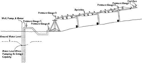
Figure 2. Center Pivot Irrigation System.
It is helpful when evaluating the pressure requirements of a pivot system to start at the far end of the system and work back to the pumping unit.
Figure 2 shows a pivot system with a well water source. The pressure at the far end of the system (gauge 1) must be sufficient to operate the last sprinkler of the irrigation system. Many times, this is a large sprinkler that requires high volume and relatively high pressures to cover areas beyond the end of the irrigation hardware.
Typical pressures range from 50 to 75 pounds per square inch (psi) for a sprinkler of this volume. Sometimes a booster pump is installed at this location to boost the pressure. This way, only the water that flows through the end gun has to be operated at a high pressure, and the water flowing through the sprinklers along the line can operate at Iow pressures.
The pressure at gauge 2 represents the pressurt at the far end of the system that is required before entering the large-volume gun. The pressure at this location is determined by the type of nozzle and sprinkler package installed on the center pivot system. The flexibility allowed when choosing a sprinkler package makes pivot systems potentially more energy efficient.
In some cases, lower pressure can be used to operate the sprinkler package on the pivot system and thereby reduce the overall energy requirements of the unit. In cases where low pressure packages are selected and an end gun is used, a booster pump would probably be needed to boost the pressure of the water flowing through the end gun.
The pressure at gauge 3-the pivot point of the irrigation system-must also be developed to operate the farthest sprinkler of the package and to overcome the flow resistance in the pipe and fittings along the system. This pressure must also overcome elevation increases from the pivot point to the highest point in the irrigated field.
Pivot systems operate on a variety of terrains and elevations as they make a revolution around a field. Because of this, pressure regulators that hold the sprinklers at the design pressure are often used on each sprinkler to ensure that they operate properly under every elevation condition.
The pressure at gauge 4 must be developed for the total system to operate satisfactorily once the water pumped from the well reaches the pivot location. The pressure reading at gauge 4 would be equal to the pressure at gauge 3 plus the pressure required to overcome the resistance in the pipe and fittings from gauge 4 to gauge 3 and the change in elevation from 4 to 3.
Pressure gauge 5 is the maximum pressure reading of the system at the discharge point of the well. This pressure would be about equal to the pressure reading at gauge 4 if the well is adjacent to the pivot. Or, the pressure could be considerably higher if the water was pumped from a long distance to the pivot and if differences in elevation existed between gauges 5 and gauges 4.
The pressure at gauge 5 is not the total dynamic head pressure of the system. To develop the total dynamic head and the total horsepower requirement of the system, the irrigation designer must know the depth from which the water is pumped. The depth from the surface of the ground to the water level is somewhat misleading.
As a well is pumped, the water level usually drops, or a draw down occurs, and the water level is lower while pumping than when the well is not operating. A good estimate of draw down is required to come up with a realistic value for the elevation that must be overcome from the groundwater to the surface of the well. Once this is determined, the frictional losses in the pipe leading from the water to the surface plus the elevation change must be added to the total pressure at gauge 5. This gives you the system's total head.
The total pressure or total dynamic head of an irrigation system is a major factor in determining the horsepower requirements of the system (1 psi = 2.37 feet of head). The following formula is used to determine the horsepower requirements of a pump:
Continuous Horsepower = Gallons Per Minute x Total Dynamic Head
3960 x Pump Efficiency
Systems that have a high total dynamic head will require more horsepower to pump water than systems that have a lower total - dynamic head. Smaller engines or power units will cost less initially and will consume less energy per hour than larger units.
Center pivot irrigation equipment is highly manageable and versatile. The option of using a medium- or low-pressure sprinkler package reduces the energy required to operate the system. Lower pressure packages are normally used on soils that readily absorb water or have a high intake rate. Lower pressure systems put the water on quicker at a given point in the field; thus, the soil must be capable of absorbing the water to prevent run-off or puddling. Pivot systems using medium- and low-pressure packages may operate from 20 to 50 psi as compared to high-pressure systems operating between 55 and 100 psi.
Publication No.
ANR-507 |
Date
June, 1988 |
Larry M. Curtis, Extension Agricultural Engineer, Professor, Biosystems and Agricultural Engineering, Ted W. Tyson, Extension Agricultural Engineer, Associate Professor, Biosystems and Agricultural Engineering |
Issued in furtherance of Cooperative Extension work in agriculture and home economics, Acts of May 8 and June 30, 1914, and other related acts, in cooperation with the U.S. Department of Agriculture. The Alabama Cooperative Extension System (Alabama A&M University and Auburn University) offers educational programs, materials, and equal opportunity employment to all people without regard to race, color, national origin, religion, sex, age, veteran status, or disability.
This document is author-produced (unedited).

