Inside the Delco 1227747...
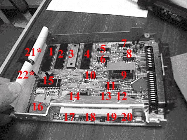
Note: the "daughterboard" is unbolted and pulled
back to view chips underneath.
| Label |
ID Number(s) |
Description |
| 1) |
21633 |
CPU |
| 2) |
16058432
16058434 |
ROM/RAM./IO |
| 3) |
58434 |
?? |
| 4) |
23263 |
Engine Control Unit |
| 5) |
43538 |
EST Interface |
| 6) |
04773 |
CMOS 4049 Hex Inverter |
| 7) |
60904
16125773(?) |
Quad Driver |
| 8) |
60904
16024824 |
Quad Driver |
| 9) |
34993
23266 |
IAC Driver |
| 10) |
04773 |
CMOS Hex Inverter |
| 11) |
?? |
?? |
| 12) |
53640
aka LM1949 |
Inj "driver" |
| 13) |
53640
aka LM1949 |
Inj "driver" |
| 14) |
35994 |
Power Supply Cntrlr |
| 15) |
23262
ADC0829
TI TL532/TL533
MC14442 |
A/D converter |
| 16) |
23264 |
Redundant Fuel Device |
| 17) |
M923 |
5v Volt Reg (pwr for board) |
| 18) |
5089 |
5v Volt Reg (pwr for sensors) |
| 19) |
M927 |
Transistor to turn on Inj |
| 20) |
M927 |
Transistor to turn on Inj |
| 21) |
323500
2732A |
4K*8 EPROM |
| 22) |
16060837 |
CALPAK |
| |
|
(See image below) |
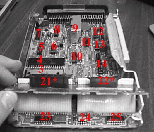
| 23) |
3265 |
Clock Generator |
| 24) |
?? |
?? |
| 25) |
?? |
?? |
| 26) |
16007757
LM9044 |
Lambda Sensor Interface Amplifier
I forgot to label it...
between 5, 6, 7, & 8 |
|
* Chips 21 and 22 are Field Replaceable Units
available thru the access door of the '7747. The
EPROM contains data tables which may be
modified to alter fuel and timing parameters. |
Most of the chip identification info and more came from Ludis Langens' web pages.
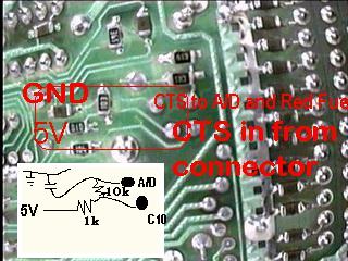
Coolant Temp Sensor Pullup Resistors...
Oh, the controversial CTS pullup...Try a
1K pullup resistor, with a 10k resistor used to connect
to the A/D and Redundant Fuel Device..and a cap connected
to GND just to clean up the signal. BTW--This image is the back
side of the board nearest the connector (close to C10--CTS).
The '7783 has a fancier method of increasing the resolution at
operating temperatures.